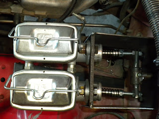
We began to install the master cylinders recently. First we had to fab a mount for them. Second we had to extend the pedal push rod. This is what we came up with.
We're going to T the front lines together and run them into one of the masters. The rear line will run into the other. No booster. No proportioning valve.
Top view of the mounting. This picture also shows the push rod integration.
The push rod with zerk fitting. Long enough to cover the distance through the firewall. Splits off into 2 ends to compress both cylinders.
Welcome
Thanks for visting! The table of contents are on the right. Archives for this blog are located at the bottom of the page.
Sunday, October 24, 2010
Monday, October 18, 2010
Rear Brakes-Install
One thing I was gonna do right this time around plumbing the brakes. I wanted them to look good. Hard lines everywhere I could to maintain better pressure. I wanted them mounted on the top of the truss so you could see them from the side. So this is what we came up with..
Stainless braided line from the body mount to the T fitting mounted in the middle of the truss. 3/16" hard lines down each side of the truss toward the calipers.
Custom made 90 degree stainless braided lines to the 1/2 ton calipers.
This is look I wanted. Something to be proud of!! You can also see we relocated the vent for the chunk of the top of the diff instead of on the axle tube. Both the vent hose and brake the will run straight up to the body. Clean look!
Front Door Panels-Install
We installed the door skins the other day. We used 1" stock to mount the skin to the door frame. To my amazement, when you open the door it doesn't rub in the front. I thought it would.
I think the side of a Cherokee looks like a sword with all the body lines progressively increasing. Damn shame the factory hides all those lines with trim.
A good view if the framing if the door skin. I wanted to keep this raw looking. In case I need to replace a panel it would be relatively easy. Of course the frame will be upholstered in black vinyl on bottom and a zipper window on top. As for opening the door, you will actually reach behind the A pillar to open the handle.
The black handle can be used to open the door after it's unlatched, but it doesn't operate the latch. Purely cosmetic.
Rock Rails-Finshing (Paint)
Sunday, October 17, 2010
Rear Truss-Finishing (Putty and Paint)
Rear Truss-Sheet metal boxing
Tapping the Knuckles
I've been running 3/4" chromoly heim joints on my steering for quite some time now. They just had 5/8" bolts with bushings inside. Well I decided to upgrade the bolts to 3/4". We decided to tap the knuckle to 3/4" thread with minimal loss to the knuckle strength. This also distributes the force on the bolt more evenly over more threads than just the nut. This also eliminates the slack in the steering which was due to the drivers' side tie rod bolt needing to be loose so the heim had room to work.
Of course the new bolt is too long. I'm just showing the difference in width.
Minimal loss of material from knuckle
Of course the new bolt is too long. I'm just showing the difference in width.
Minimal loss of material from knuckle
Friday, October 8, 2010
Rock Rail Skid Plates-Final Install
David installed the passenger side yesterday. Used 3/8" countersunk bolts. Some of the areas (including the front spring hanger) needed to be reinforced so the skid plate didn't crush inward. He used some steel angle to fill in those areas.
We still need to trim this piece off. (Passenger wheel arch)
Thursday, October 7, 2010
Manual Brakes-Unboxing
Purchased these yesterday. Manual brakes from Wildwood and US Brakes. This setup is designed around working when the motor isn't running. That way you still have brakes coming down a steep hill if the motor cuts out. In addition, I"m going to run two master cylinders. One for each axle. If one quits, the other will still stop.
This will allow me to remove the stock brake booster, proportioning valve, and the adjustable proportioning valve I had on the rear brakes. Basically freeing up alot of space under the hood in preperation for front shock hoops.
Rock Rail Skid Plates
Don't know what to call these. Not really boatsides, but it's the same idea. I sourced some 1/2" polycarbonate skid plates to cover the distance between the rock rails and the frame. Yes, I said frame, because I now have one.
Mitered to a 45 to keep anything from catching.
Notched out to accomodate the front spring hanger.
Front passenger side.
Mitered to a 45 to keep anything from catching.
Notched out to accomodate the front spring hanger.
Front passenger side.
Traction Bar-Final Install
Wrapped around the axle to prevent the mount from busting loose.
Change the design to a high clearance design. 1.25" .120 wall DOM
Body mount. We had to push the floor pan up a bit to accomodate the height of the shackle. Gusseted across the back.
David welded a 5 " piece of DOM into the frame. Tapped it and now the shackle has something to thread into.
Change the design to a high clearance design. 1.25" .120 wall DOM
Body mount. We had to push the floor pan up a bit to accomodate the height of the shackle. Gusseted across the back.
David welded a 5 " piece of DOM into the frame. Tapped it and now the shackle has something to thread into.
Soft Doors-Handles Installed
Rear Truss-The Beginning
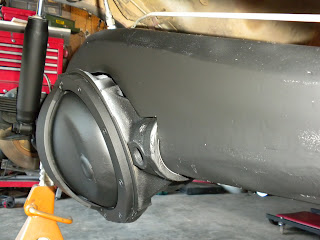
Began the process of trussing the rear axle. Used 1.75" electric weld tubing to span the distance between spring perches. We intend on boxing in the tubing on both sides.
Something had to give. Since the traction bar was already installed and wrapped we decided to cut it out of the truss.
View from inside the right rear wheel arch.
Something had to give. Since the traction bar was already installed and wrapped we decided to cut it out of the truss.
View from inside the right rear wheel arch.
Subscribe to:
Posts (Atom)