
Sunday, June 3, 2012
Roll Cage coming this week
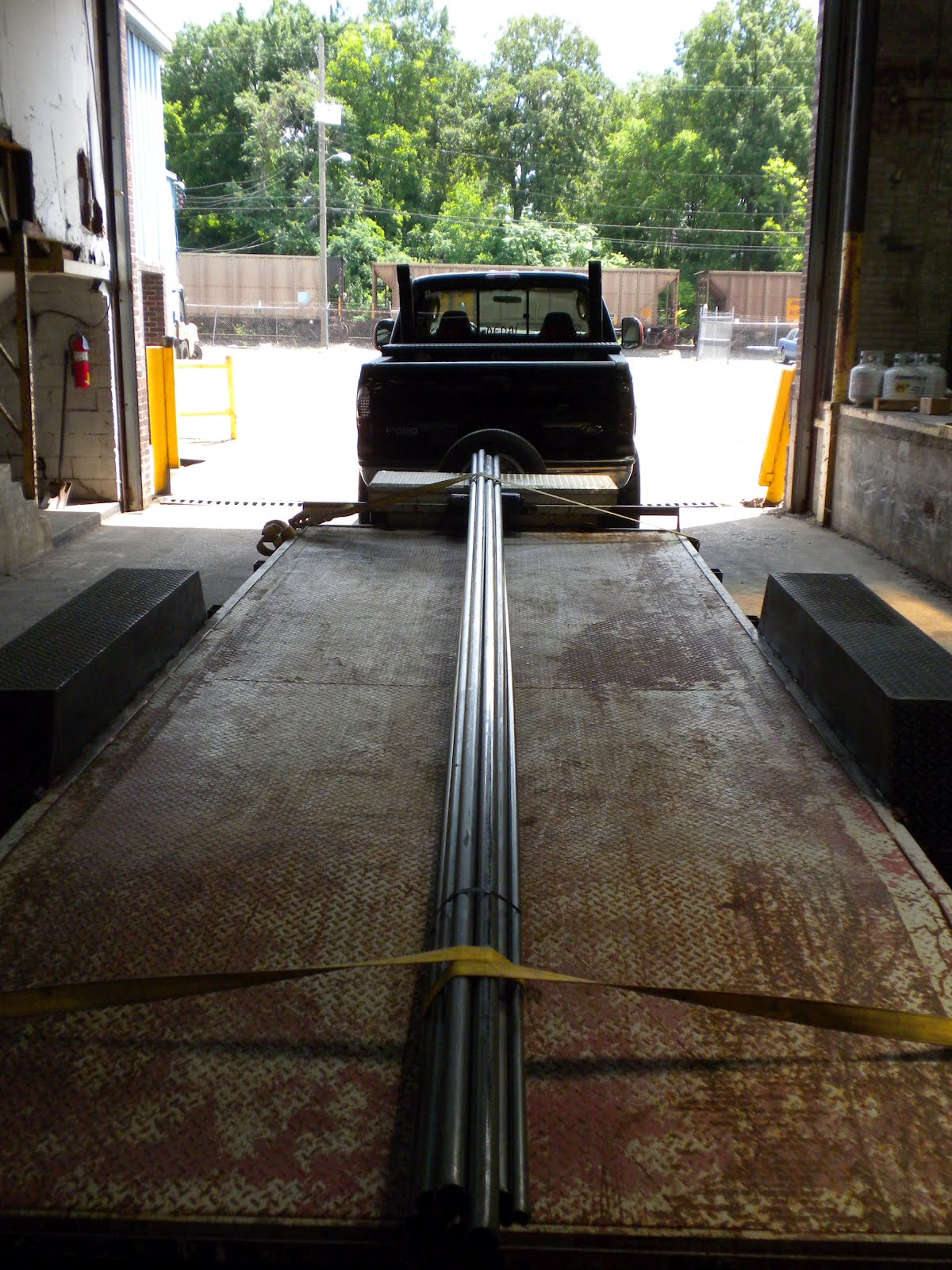
I delivered my Jeep to the Offroad Connection in Fultondale this past Friday. Keith (The owner) said they would be starting on the interior cage this week. I will be uploading quite a few pictures during the process. Not just one or two, I will be publishing daily so check back frequently. I expect the process to take 2-3 weeks of on/off work. During the process I will be sharing dimensions, bend angles, tips and tricks, design ideas and loads of pictures.
Thursday, May 3, 2012
Interior Roll Cage-Tubing Acquisition
Today David and I went to BesCo Steel to pick up tubing in preparation of the new interior cage. I purchased (8) 20ft. sticks of 1.75"OD x .120" wall electric weld and (3) 20ft. sticks of 1"OD x .062" wall electric wall. All of the cage will be done with the 1.75"OD and the trim work around the dash will be done with the 1"OD.
 Thanks to David for hauling it for me.
 Here is a sneak peak of the 1/10th scale model I'm building of the roll cage. There will be a post on in the future.


Monday, April 30, 2012
Yardsale
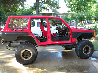
Well I finally brought the Jeep home from Grayrock (in my secret hiding location). It's been up there for close to two months. In preparation of the interior cage I have removed the passenger seat, rear door skins, front soft doors and skins and marguard windshield. I have degreased everything and washed the outside clean. This week I will be buying the steel tubing I will need for my interior roll cage. Keith is allowing me to store it at the ORC until he gets time for me. So I'll be doing that this week.


 While I have some down time I have quite a few things I need/want to do:
-Service front end bearings, fluid, etc.
-Change rear diff/ fluid
-Install HID headlights
-Repaint interior
-Repaint rear quarter panel guards
-Change joints in front drive shaft
-Check/replace brakes
-Diagnose/fix/upgrade rear rock light
-Buy front bumper
-Re-install winch
While I have some down time I have quite a few things I need/want to do:
-Service front end bearings, fluid, etc.
-Change rear diff/ fluid
-Install HID headlights
-Repaint interior
-Repaint rear quarter panel guards
-Change joints in front drive shaft
-Check/replace brakes
-Diagnose/fix/upgrade rear rock light
-Buy front bumper
-Re-install winch


Tuesday, January 24, 2012
PCV/CCV breather
After I removed the stock PCV & CCV hoses that recirculated oil and its vapors through my intake, I replaced it with valve cover breathers from Moroso. Unfortunately these fill up with oil from blowback and that restricts the breathing of the motor. So I decided to pick up an Allstar catch can/breather. It's main feature is it allows the can to fill up with fluid but it's breather is at the top so it doesn't restrict the air flow.
I picked up these PCV elbows at Napa for cheap. I'm sure the dealership wanted $20ea. I used the new wire clamp system instead of a hose clamp. Looks way better.

I fabbed up a cradle to hold the breather from being flat. This way the fluid stays at the bottom and the breather stays dry. There are baffles inside the can to prevent the fluid from splashing around.


It barely fits inside the cowl. I had to put 90 degree fittings on the can, otherwise it wouldn't have fit. I'm still a little concerned with all the off camber stuff I do that fluid will still finds its way to saturating the breather and starve the motor of air. I will have to check it regularly.

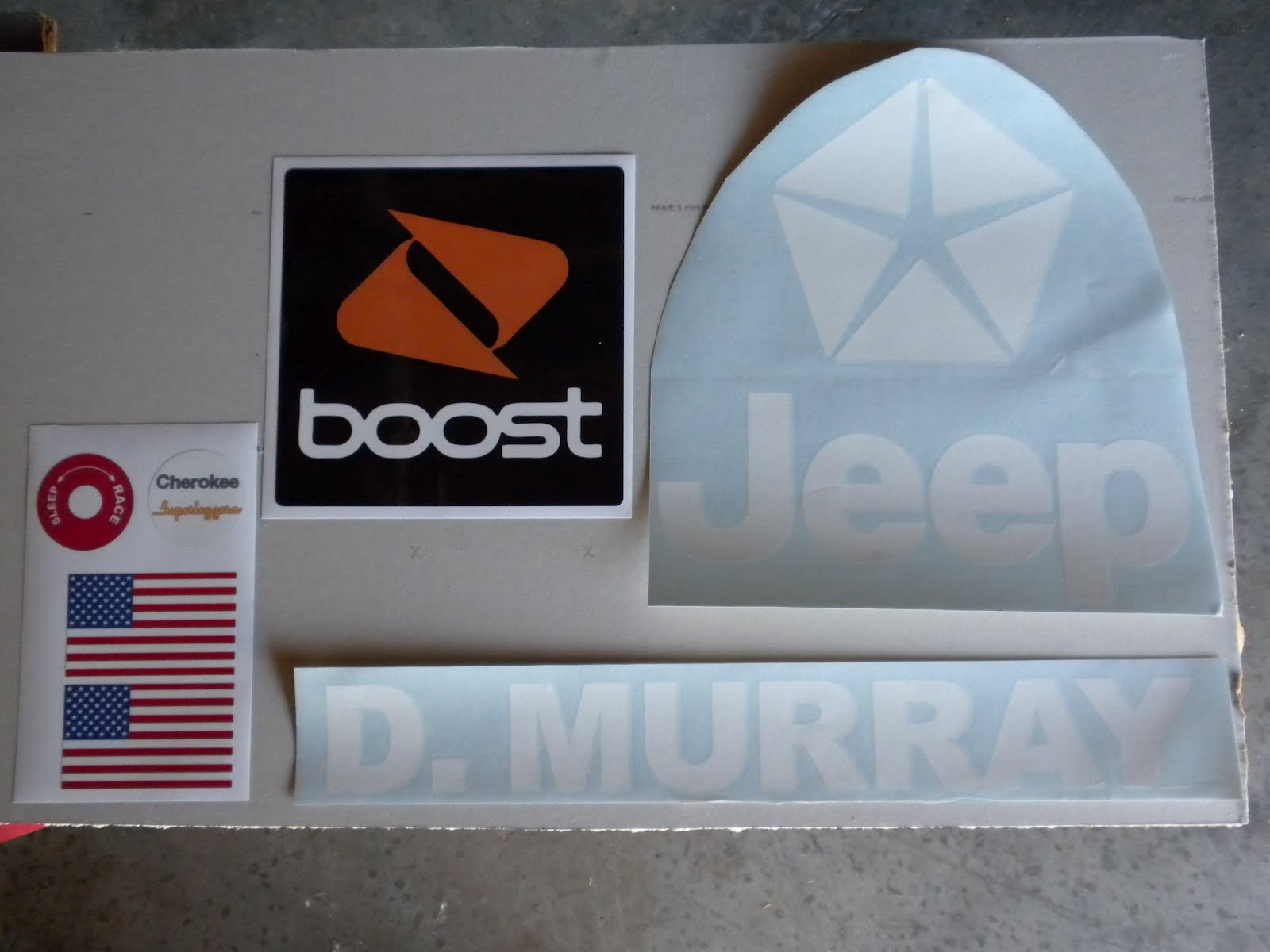
Sticker Pack #2
I went to the printer's the other week. Picked up my second set of stickers for the Jeep. This time I had them printed from Chris at Alotta Graphics in Birmingham. Nice guy, quick turn around, fair price, I'd recommend him. I emailed him the designs and he printed them on very sticky vinyl.
I'm not going to use the D. Murray and American Flag (pictured here). I'm going to have them reprinted in black. There were a couple other stickers he printed that are not pictured here.

The steering wheel center logo.

Master disconnect


Jeep/Chrysler pentastar logo

Boost logo

I'm not going to use the D. Murray and American Flag (pictured here). I'm going to have them reprinted in black. There were a couple other stickers he printed that are not pictured here.
The steering wheel center logo.

Master disconnect


Jeep/Chrysler pentastar logo

Boost logo

Friday, December 16, 2011
Sandwich Oil Adapter and Cooler- Install
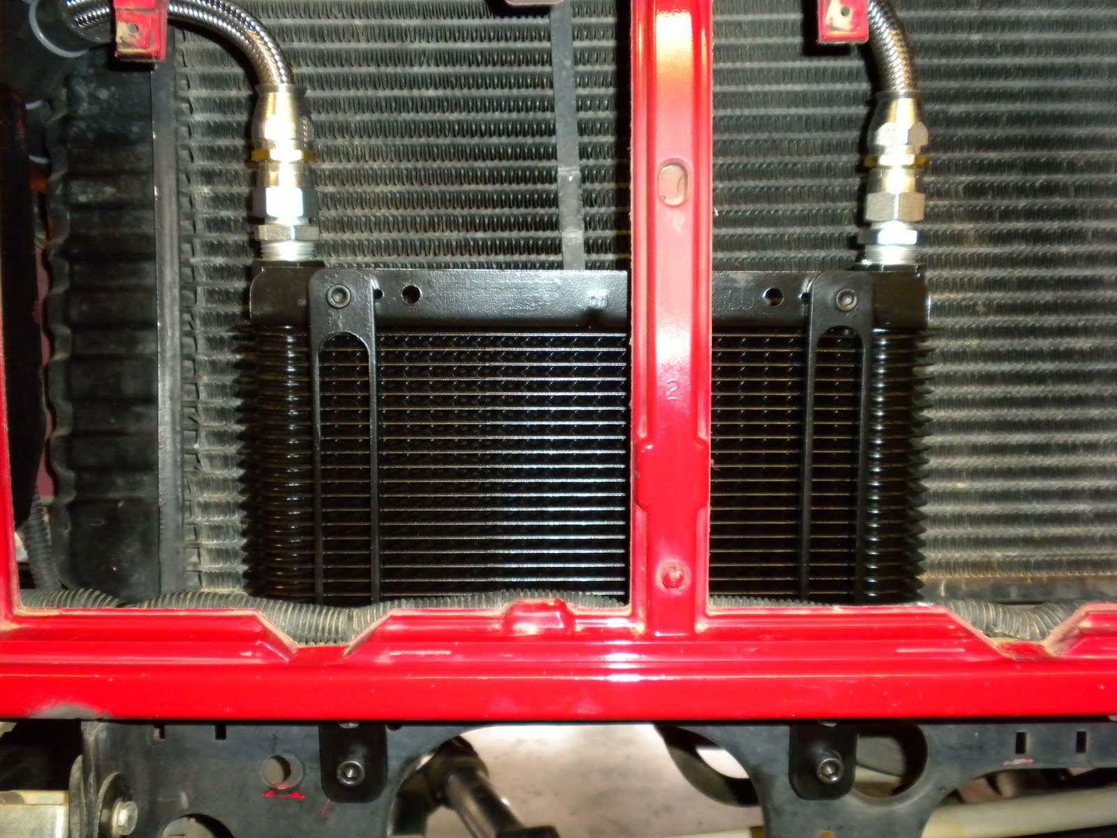
The final install for the oil cooler has begun. I recently purchased a 6"x11" deck mount cooler. I had to adapt the female #8an fittings on the SS hoses to the pipe thread on the cooler. No problem. In addition, I had to fab up some mounts for the cooler which will sit in front of the radiator. So off to the ORC for a couple hours to make something custom.
I started with 1" stock cut down to the length I needed and drilled some holes for mounting.

Rounded off the corners and milled out the middle with an 11/16" bit. Slapped a coat of semi-flat black and there you have it.

It will allow for that much more air to pass through the cooler.

It looks good mounted and it's strong, it's not going anywhere.

The sandwich adapter is installed where your filter used to be. The one side of the adapter that has an O ring will face inward, to meet up with the factory filter mount. The entire sandwich piece is held down by a threaded bung. It holds the new adapter down snugly and provides the same 3/4" x 16 thread pitch that the factory did.

I sill have plenty of room to run the Wix 1515 filter. Originally the factory called for 6 quarts of oil, but considering the lines to and from the cooler I think it's going to add another 2 quarts.
-Pro's
-Cooler oil
-More oil
-Looks Good
-Con's
-Slightly pricey at approx. $300 for these fittings and setup. It could be done for less with rubber hoses and pipe fittings, but you would run the risk of looking like a plumber did the install.
I started with 1" stock cut down to the length I needed and drilled some holes for mounting.

Rounded off the corners and milled out the middle with an 11/16" bit. Slapped a coat of semi-flat black and there you have it.

It will allow for that much more air to pass through the cooler.

It looks good mounted and it's strong, it's not going anywhere.
The sandwich adapter is installed where your filter used to be. The one side of the adapter that has an O ring will face inward, to meet up with the factory filter mount. The entire sandwich piece is held down by a threaded bung. It holds the new adapter down snugly and provides the same 3/4" x 16 thread pitch that the factory did.

I sill have plenty of room to run the Wix 1515 filter. Originally the factory called for 6 quarts of oil, but considering the lines to and from the cooler I think it's going to add another 2 quarts.
-Pro's
-Cooler oil
-More oil
-Looks Good
-Con's
-Slightly pricey at approx. $300 for these fittings and setup. It could be done for less with rubber hoses and pipe fittings, but you would run the risk of looking like a plumber did the install.
Tuesday, November 1, 2011
Grant Gt Steering Wheel- Installation
It was time to put this on. I got tired of looking at it on my bookshelf and even though I have no cage and no dash, I decided it was time. I borrowed the puller from Keith at ORC, brought it back to my garage and began to disassemble my steering column. I have no airbag, that was removed quite a while ago, so it really didn't involve much.
You'll need a puller, unless you just press against the back of the wheel with both knees and the wheel flies off and breaks your nose. So yeah...you'll need a puller.

Where I began. No horn, no airbag.

Remove the horn cover and you'll see where your airbag should be. We already set this off (on purpose) so you only see the frame. You also see the steering shaft nut, which needs to be removed.

Remove the steering shaft nut.

The airbag frame needs to be removed also. 2 nuts.

This is when you use the puller. Pretty easy, especially when you watch someone else do it. Thanks Josh.

After removing the wheel, you're left with the end of the steering shaft. The threads and the splines need to be cut off as to leave the larger diameter shaft so the quick disconnect collar will slide over and be welded on.

Thanks David for bringing your welder over and taking care of this for me.

He slid the collar out off the shaft a bit to create a hole he could fill with weld.

I removed the windshield wiper control arm (I no longer have wipers) and trimmed down the turn signal/high beam control arm quite a bit because it was getting in the way of the wheel, which sits a lot closer to the column housing. So close I have to move my seat forward now. I still have to put the plastic trim back on.

Saturday, October 29, 2011
Front End Alignment
It's time for another front end alignment after replacing tie rod heim joints and especially after I noticed my spindle nuts were only hand tight when I did my last alignment. So I was sure the toe was off. Since my tie rod was built with left and right threaded heims it allows me to adjust it on my own. Here's the technique..
Put the front end on jack stands so the front tires spin freely.

I built some kind of contraption that held a scraper tightly in place. A screwdriver would work just as well. A vice would be even better. But the point is to scribe a line around the circumference of the tire. You must hold the scraper/screwdriver tightly in place so the line remains straight.

Marry the scraper to the tire so that's it's close enough to make contact with the tire and scribe a line in the rubber.

I stood on the wood blocks that held the scraper down so it wouldn't move and spun the tire 360 degrees. Do both tires the same way.

Measure the distance between the lines in the front of tires.

Measure the distance between the line in the back of the tires.

If the front measurement is less than the rear, you're toe'd in. If the rear measurement is less than the front you're toe'd out. Essentially you want your tires to toe in 3/8"-1/2". I was at toe'd in at 5/8" and as a result I need to turn the tie rod heim joints inward a turn or two and re-measure to bring that down to 1/2".
Trimming lug nuts
The first time I saw this I was at a pre-race inspection for the XRRA. They insisted that all lug nuts be "uncapped" so that a visual inspection could be performed at any time. It also prevents any build up of dirt from staying inside the lug. So I grinded off the cap and cleaned up the threads and re-installed.


Now when my OCD kicks in I just have to glance at the stud to see if anything has loosened up.


Now when my OCD kicks in I just have to glance at the stud to see if anything has loosened up.

Drag link updated parts
I installed new hardware on the drag link. New grade 8 bolts, chromoly heims joints, and alignment spacers. There was some slack in the heims (after 3 years without changing them), it was kind of expected. Now I can move on to the front end alignment knowing that all heims have been replaced and there will be no slack in the steering.


Friday, October 28, 2011
8.25 Chunk Cover Threaded Bung
After taking the rear chunk cover off to do a fluid change, I realized the rubber plug was beginning to deteriorate and needed replaced. So I opted to have the unthreaded bung cut out and replaced with the threaded bung from a D60. Originally we thought it needed to be cut out with a plasma, but then realized a hole saw would work just fine.
Untouched original cover

Rubber plug on left. Plasma cut threaded bung on right.

Interior view untouched cover.

Interior view threaded bung welded to outside of cover.

Finished product. I'm not grinding anymore. I don't want to compromise the integrity of the welds.

3/4" tapered pipe thread plug with a 9/16" sunken hex head.


Subscribe to:
Posts (Atom)